Iranian Classification Society Rules

< Previous | Contents | Next >
Section 30 Protective Coating Systems for Ballast Tanks
3001. Application
1. The requirements of this Section apply to tests and inspection for the type approval of protective coating systems in accordance with the requirements in Pt 3, Ch 1, 803. of the Guidance.
2. Winter and summer type coating are considered different unless infrared (IR) identification and spe- cific gravity (SG) demonstrates that they are the same. Winter type epoxy is required separate pre- qualification test including shop primer compatibility test according to 3006.
3002. Data to be submitted
1. The following approval data are to be submitted to the Society in addition to those specified in
102.
(1) Copy of Technical Data Sheet, including : 3 copies
(a) product name and identification mark and/or number;
(b) materials, components and composition of the coating system, colours;
(c) minimum and maximum dry film thickness;
(d) application methods, tools and/or machines;
(e) condition of surface to be coated (de-rusting grade, cleanness, profile, etc.); and
(f) environmental limitations (temperature and humidity);
(g) dry-to recoat times and walk-on time
(2) Compatibility of shop primer with protective coating system : 3 copies(if any)
(3) Inspection and acceptance criteria of protective coating system : 3 copies
(4) Procedures for repair of protective coating system : 3 copies
2. The coating manufacturer should provide to the Society the following information;
(1) A detailed list of the production facilities.
(2) Names and location of raw material suppliers will be clearly stated.
(3) A detailed list of the test standards and equipment to be used, (Scope of approval).
(4) Details of quality control procedures employed.
(5) Details of any sub-contracting agreements.
(6) List of quality manuals, test procedures and instructions, records, etc.
(7)
Copy of any relevant certificates with their issue number and/or date e.g. Quality Management System certification.
3003. Data review and plant audit
1. The Society shall performed the data review and plant audit specified in Pt. 1, Annex 1-11, 2. and 3. of the Guidance Relating to the Rules for the Classification of Steel Ships to assure the manufacturing process (including that of subcontractor's works) and quality assurance of the pro- tective coating systems.
2. With the exception of early ‘scale up’ from lab to full production, adjustment outside the limi- tations listed in the QC instruction referred to below is not acceptable, unless justified by trials during the coating system’s development programme, or subsequent testing. Any such adjustments must be agreed by the formulating technical centre.
3. If formulation adjustment is envisaged during the production process the maximum allowable limits will be approved by the formulating technical centre and clearly stated in the QC working procedures.
4. The manufacturer’s quality control system will ensure that all current production is the same for- mulation as that supplied for the Type Approval Certificate. Formulation change is not permissible without testing in accordance with the test procedures in 3004. 3. or 4. and the issue of a Type Approval Certificate by the Society.
5. Batch records including all QC test results such as viscosity, specific gravity and airless spray char- acteristics will be accurately recorded. Details of any additions will also be included.
Guidance for Approval of Manufacturing Process and Type Approval, Etc. 2015 203
![]()
6. Whenever possible, Exceptions may be
raw material supply and lot details for each coating batch will be traceable. where bulk supply such as solvents and pre-dissolved solid epoxies are stored
in tanks, in which case it may only be possible to record the supplier’s blend.
7. Dates, batch numbers and quantities supplied to each coating contract will be clearly recorded.
8. All raw material supply must be accompanied the supplier’s ‘Certificate of Conformance’. The cer- tificate will include all requirements listed in the coating manufacturer’s QC system.
9. In the absence of a raw material supplier’s certificate of conformance, the coating manufacturer must verify conformance to all requirements listed in the coating manufacturer’s QC system.
10. Drums must be clearly marked with the details as described on the ‘Type Approval Certificate’.
11. Product Technical Data Sheets must comply with all the PSPC requirements. The QC system will ensure that all Product Technical Data Sheets are current.
12. QC procedures of the originating technical centre will verify that all production units comply with the above stipulations and that all raw material supply is approved by the technical centre.
3004. Performance standard
1. Protective coating systems are, in principal, to be an epoxy-based systems. All systems that are not an epoxy-based system applied according to this requirements are defined as an alternative system.
2. A multi-coat system with each coat of contrasting colour is recommended. The top coat shall be of a light colour(a colour that reflects light to an extent that a simple flash light (hand torch) will make inspection easy and fast. Normally light grey, buff, off-white, swimming pool blue/green, etc. easily distinguishable from rust.) in order to facilitate in-service inspection.
3. Protective coatings for dedicated seawater ballast tanks shall satisfied the approval tests specified in 3006. 2. and 3. and protective coatings for double-side spaces of bulk carriers shall satisfied the approval test specified in 3006. 3.
4. Epoxy-based systems which have documented field exposure for 5 years with a final coating con- dition of not less than "GOOD" may be accepted. In this case, field exposure for 5 years shall be satisfied following conditions.
(1) Coating manufacturer’s records, which shall at least include the information indicated in follow- ings, shall be examined to confirm coating system has 5 years field exposure, and the current product is the same as that being assessed.
(a)
Original application records
(b) Original coating specification
(c)
Original technical data sheet,
(d) Current formulation’s unique identification (Code or number)
(e)
(f)
If the mixing ratio of base and curing agent has changed, a statement from the manu- facturer confirming that the composition mixed product is the same as the original
composition. This shall be accompanied by an explanation of the modifications made.
Current technical data sheet for the current production site
(g) SG and IR identification of original product
(h) SG and IR identification of
the current product
(i)
If original SG and IR cannot be provided then a statement from the manufacturer confirm- ing the readings for the current product are the same as those of the original.
(2) A joint (coating manufacturer/Society) survey of all ballast tanks of a selected vessel is to be carried out for the purpose of verification of compliance with the requirements of (1) and (5). The coating manufacturer’s representative is to be qualified to NACE Coating Inspector Level 2 or FROSIO Inspector Level III or equivalent as verified by the Administration.
(3) The selected vessel is to have ballast tanks in regular use, of which:
(a) At least one tank approx 2,000 ㎥
(b) At least one tank shall be adjacent to heated tank and
(c) At least one tank underdeck exposed to sun.
(4) In the case that the selected vessel does not meet the requirements in (3) above then the limi- tations shall be clearly stated on the type approval certificate. For example, the coating cannot be used in tanks adjacent to heated tanks or underdeck or tanks with volume greater than the
204 Guidance for Approval of Manufacturing Process and Type Approval, Etc. 2015
![]()
size surveyed.
(5) All ballast tanks shall be in "GOOD" condition excluding mechanical damages, without touch up or repair in the prior 5 years. “Good” is defined as: Condition with spot rusting on less than 3% of the area under consideration without visible failure of the coating. Rusting at edges or welds, must be on less than 20 % of edges or welds in the area under consideration. Examples of how to report coating conditions with respect to areas under consideration should be as those given in IACS Recommendation 87, Appendix 1.
5. In the case that a manufacturer wishes to have products which are manufactured in different loca- tions under the same name, then infrared (IR) identification and specific gravity shall be used to demonstrate that they are the same coating, or individual approval tests will be required for the paint manufactured in each location.
3005. Test Laboratory
The test laboratory where testing is carried out in accordance with the requirements in 3004. 3. are to equip the test facilities so that they can perform the testing in accordance with the require- ments in this Instruction and are to be data reviewed and audited in accordance with the require- ments in Pt 1, Annex 1-11, 2.(except for (3) (A) (b)) and 3. of the Guidance Relating to the Rules for the Classification of Steel Ships by the Society.
3006. Type test
1. Application of protective coating system
(1) There shall be a minimum of two stripe coats and two spray coats, except that the second stripe coat, by way of welded seams only, may be reduced in scope where it is proven that the NDFT can be met by the coats applied, in order to avoid unnecessary over-thickness.
(2) Stripe coats shall be applied by brush or roller.
(3) Each main coating layer shall be appropriately cured before application of the next coat, in ac- cordance with coating manufacturer’s recommendations.
(4) Surface contaminants such as rust, grease, dust, salt, oil, etc., shall be removed prior to painting
with proper method according to the paint manufacturer’s recommendation. Abrasive inclusions embedded in the coating shall be removed. Job specifications shall include the dry-to-recoat times and walk-on time given by the manufacturer.
(5) NDFT 320 ㎛ with 90/10 rule(A 90/10 rule means that 90 % of all thickness measurements
shall be greater than, or equal to, NDFT and none of the remaining 10 % measurements shall be below 0.9 x NDFT) for epoxy-based coatings; other systems to coating manufacturer’s
specifications.
(6) For the coating pre-qualification test, the measured average DFT(dry film thickness) on each prepared test panels shall not exceed NDFT(nominal dry film thickness) of 320 ㎛ plus 20 %
unless a paint manufacturer specified a NDFT greater than 320 ㎛.
(7) In the case that a paint manufacturer specified a NDFT greater than 320 ㎛, the average DFT
shall not exceed the specified NDFT plus 20 % and the coating system shall be certified to the
specified NDFT if the system passes the tests according to 3004. 3.. The measured DFT shall meet the "90/10" rule and the maximum DFT shall be below the maximum DFT value speci- fied by the manufacturer.
(8) Care shall be taken to avoid increasing the thickness in an exaggerated way. Wet film thickness shall be regularly checked during application.
(9) Thinner shall be limited to those types and quantities recommended by the manufacturer.
2. Test on Simulated Ballast Tank Conditions
(1) Test condition
Test on simulated ballast tank conditions shall satisfy each of the following conditions:
(a) The test shall be carried out for 180 days.
(b) There are to be 5 test panels.
(c) The size of each test panel is 200 mm x 400 mm x 3 mm. Two of the panels (Panel 3 and
4 below) have a U-bar welded. The U-bar is welded to the panel in a 120 mm distance
from one of the short sides and 80 mm from each of the long sides. (see Fig 3.30.1)
Guidance for Approval of Manufacturing Process and Type Approval, Etc. 2015 205
![]()
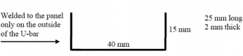
Fig 3.30.1 Welding of U-bar
(d) Coating systems are to be applied on test panels according to 6.1. Shop primer(zinc con- taining inhibitor free zinc silicate based or equivalent) to be weathered for at least 2 months and cleaned by low pressure washing or other mild method. Blast sweep or high pressure washing, or other primer removal methods not to be used. Weathering method and extent shall take into consideration that the primer is to be the foundation for a 15 year target useful life system. To facilitate innovation, alternative preparation, coating systems and dry film thicknesses may be used when clearly defined.
(e)
(f)
The reverse side of the test piece shall be painted appropriately, in order not to affect the test results.
As simulating the condition of actual ballast tank, the test cycle runs for two weeks with natural or artificial seawater and one week empty. The temperature of the seawater is to be kept at about 35°C.(see Fig 3.30.2)
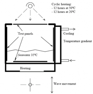
Fig 3.30.2 Wave tank for testing of ballast tank coatings
(g) Test panel 1: This panel is to be heated for 12 h at 50 °C and cooled for 12 h at 20 °C in order to simulate upper deck condition. The test panel is cyclically splashed with natural or artificial seawater in order to simulate a ship’s pitching and rolling motion. The interval of splashing is 3 s or faster. The panel has a scribe line down to bare steel across width.
(h) Test panel 2: This panel has a fixed sacrificial zinc anode in order to evaluate the effect of cathodic protection. A circular 8 mm artificial holiday down to bare steel is introduced on the test panel 100 mm from the anode in order to evaluate the effect of the cathodic protection. The test panel is cyclically immersed with natural or artificial seawater.
(i) Test panel 3: This panel is to be cooled on the reverse side, in order to give a temper- ature gradient to simulate a cooled bulkhead in a ballast wing tank, and splashed with natu- ral or artificial seawater in order to simulate a ship’s pitching and rolling motion. The gra- dient of temperature is approximately 20 °C, and the interval of splashing is 3 s or faster. The panel has a scribe line down to bare steel across width.
206 Guidance for Approval of Manufacturing Process and Type Approval, Etc. 2015
![]()
(j) Test panel 4: This panel is to be cyclically splashed with natural or artificial seawater in order to simulate a ship’s pitching and rolling motion. The interval of splashing is 3 s or faster. The panel has a scribe line down to bare steel across width.
(k) Test panel 5: This panel is to be exposed to dry heat for 180 days at 70 °C to simulate boundary plating between heated bunker tank and ballast tank in double bottom.
(2) Test results
(A) Prior to the testing, the following measured data of the coating system shall be reported:
(a)
Infrared (IR) identification of the base and hardener components of the coating;
(b) Specific gravity of the base and hardener components of the paint(refer to KS M ISO
2811-1/4); and
(c)
Number of pinholes, low voltage detector at 90 V.
(B) After the testing, the following measured data shall be reported:
(a)
blisters and rust (refer to KS M ISO 4628-2 and KS M IS O 4628-3);
(b) dry film thickness (DFT) (use of a template)(9 equally distributed measuring points are used on panel’s size 150 mm x 150 mm or 15 equally distributed measuring points on panel’s size 200 mm x 400 mm.);
(c)
adhesion value(refer to KS M ISO 4624);
(d) flexibility modified according to panel thickness (refer to AST M D 4145, 3 mm steel, 300
μm coating, 150 mm cylindrical mandrel gives 2 % elongation) for information only;
(e)
cathodic protection weight loss/current demand/disbondment from artificial holiday; and
(f) undercutting from scribe. The undercutting along both sides of the scribe is
measured
and the maximum undercutting determined on each panel. The average of the three
maximum records is used for the acceptance.
(3) Acceptance criteria
(a) The test results based on (2) shall satisfy the criteria specified in Table 3.30.1.
Table 3.30.1. Acceptance criteria for the test on Simulated Ballast Tank Conditions
Item | Acceptance criteria for epoxy-based systems | Acceptance criteria for alternative systems |
Blisters on panel | No blisters | No blisters |
Rust on panel | Ri 0 (0%) | Ri 0 (0%) |
Number of pinholes | 0 | 0 |
Adhesive failure | > 3.5 MPa Adhesive failure between substrate and coating or between coats for 60% or more of the areas. | > 5 MPa Adhesive failure between substrate and coating or between coats for 60% or more of the areas. |
Cohesive failure | > 3 MPa Cohesive failure in coating for 40% or more of the area. | > 5 MPa Cohesive failure in coating for 40% or more of the area. |
Cathodic protection; current demand calculated from weight loss | < 5 mA/m2 | < 5 mA/m2 |
Cathodic protection; disbondment from artificial holiday | < 8 mm | < 5 mm |
Undercutting from scribe | < 8 mm | < 5 mm |
U-bar | Any defects, cracking or detachment at the angle or weld will lead to system being failed. | Any defects, cracking or detachment at the angle or weld will lead to system being failed. |
Guidance for Approval of Manufacturing Process and Type Approval, Etc. 2015 207
![]()
(b) Epoxy-based systems shall satisfy the criteria for epoxy-based systems and alternative sys- tems shall satisfy the criteria for alternative systems as indicated in Table 3.30.1.
(4) Test report
The test report shall include the following information:
(A) name of the manufacturer;
(B) date of tests;
(C) product name/identification of both paint and primer;
(D) batch number;
(E) data of surface preparation on steel panels, including the following:
(a) surface treatment;
(b) water soluble salts limit;
(c) dust; and
(d) abrasive inclusions;
(F) application data of coating system, including the following:
(a) shop primed;
(b) number of coats;
(c)
recoat interval(both of actual specimen data and manufacturer’s require- ment/recommendation.)
(d) dry film thickness (DFT) prior to testing(both of actual specimen data and manu- facturer’s requirement/recommendation);
(e)
(f)
thinner;(both of actual specimen data and manufacturer’s requirement/recommendation);
humidity(both of actual specimen data and manufacturer’s requirement/recommendation);
(g) air temperature(both of actual specimen data and manufacturer’s requirement/ recom- mendation);
(h) steel temperature;
(G) test results according to (2); and
(H) judgment according to (3)
3. Condensation Chamber Test
(1) Test condition Condensation chamber test shall be conducted in accordance with the KS M ISO 6270-1 and shall satisfy each of the following conditions (see Fig 3.30.3):
(a)
The exposure time is 180 days.
(b) There are to be 2 test panels.
(c)
The size of each test panel is 150 mm x 150 mm x 3 mm.
(d) Coating system are to be applied on test panels according to 6.1 of this Instruction. Shop primer to be weathered for at least 2 months and cleaned by low pressure washing or other mild method. Blast sweep or high pressure washing, or other primer removal methods not to be used. Weathering method and extent shall take into consideration that the primer is to be the foundation for a 15 year target life system. To facilitate innovation, alternative prepara- tion, coating systems and dry film thicknesses may be used when clearly defined.
(e)
The reverse side of the test piece shall be painted appropriately, in order not to affect the test results.
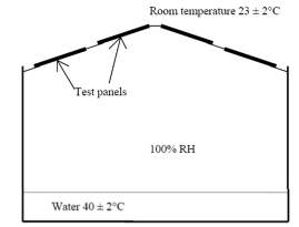
Fig 3.30.3 Condensation chamber
208 Guidance for Approval of Manufacturing Process and Type Approval, Etc. 2015
![]()
(2) Test results According to 2. (2), (A) and (B) (except for 2. (2) (B), (e) and (f))
(3) Acceptance criteria
(A) The test results based on (2) shall satisfy the criteria specified in Table 3.30.2.
Table 3.30.2. Acceptance criteria for the Condensation Chamber Test
Item | Acceptance criteria for epoxy-based systems | Acceptance criteria for alternative systems |
Blisters on panel | No blisters | No blisters |
Rust on panel | Ri 0 (0%) | Ri 0 (0%) |
Number of pinholes | 0 | 0 |
Adhesive failure | > 3.5 MPa Adhesive failure between substrate and coating or between coats for 60% or more of the areas. | > 5 MPa Adhesive failure between substrate and coating or between coats for 60% or more of the areas. |
Cohesive failure | > 3 MPa Cohesive failure in coating for 40% or more of the area. | > 5 MPa Cohesive failure in coating for 40% or more of the area. |
(B) Epoxy-based systems shall satisfy the criteria for epoxy-based systems and alternative tems shall satisfy the criteria for alternative systems as indicated in Table 3.30.2.
(4) Test report According to 2. (4)
4. Equivalent laboratory test
sys-
Type approval of a coating system is normally to be carried out in accordance with 2 and/or 3 above. However, the Society may accept an equivalent laboratory test method comprised of a single test or number of tests combined as a test procedure, subject to the following acceptance require- ments:
(1) The test method/programme shall be based on recognized national or international standards, well established with proven experience.
(2) The equivalent test program is to adequately address the technical intent of the tests required in
2 and/or 3 above.
(3) Test results of samples tested in accordance with the equivalent test methods are, wherever pos- sible, to be compared against the acceptance criteria specified in 2 and/or 3 above. Where this is not possible due to the parameters of the equivalent test method used, the acceptance criteria of the equivalent test method standard are to be selected that provide the closest equivalent to those in 2 and/or 3 above.
(4) Test laboratories shall comply with 3005.
(5) Epoxy based coating systems approved by such an equivalent test method shall be applied in the shipyard in accordance with all the surface preparation and application requirements specified in 1 above.
3007. Type Approval Certificates
1. If the type tests specified in 3004. 3 or 5 years field exposure test specified in 3004. 4 are sat- isfactory, a Type Approval Certificate will be issued to include both the epoxy and the shop primer.
2. In case where 5 years field exposure test specified in 3004. 4 are performed, The Type Approval Certificate shall reference the joint survey report specified in 3004. 4. (2)
3. In case where 5 years field exposure test specified in 3004. 4 are performed, If the applied NDFT is greater than required in 3006. 1. (5), the applied NDFT will be the minimum to be applied during construction. This will be reported prominently on the Type Approval Certificate.
Guidance for Approval of Manufacturing Process and Type Approval, Etc. 2015 209
![]()
4. In case where the epoxy has been tested without shop primer on bare prepared steel with sat- isfactory, a Type Approval Certificate will be issued. The Type Approval Certificate will just re- cord the epoxy.
5. The Type Approval Certificate is invalid if the formulation of either the epoxy or the shop primer is changed. It is the responsibility of the manufacturer to inform class immediately of any changes to the formulation.
3008. Compatability of shop primer
1. If a zinc silicate shop primer has passed the type test as part of an epoxy coating system, it may be used in combination with other approved epoxy coatings provided that the compatibility has been confirmed by the test in accordance with 3006. 2. (1), (h) without wave movement.
2. In case where same epoxy coating system is to applied on the different shop primers, each combi- nation to be type tested in accordance with 3004.. However, if each shop primer have already passed the type test as part of an epoxy coating system, the compatibility of shop primer can be confirmed by the test in accordance with 1. above.
3. If the test or tests specified above 1. are satisfactory, a Type Approval Certificate will be issued.
In this instance the Type Approval Certificate will include the details of the epoxy and a list of all shop primers with which it has been tested that have passed these requirements.
3009. Dealing after approval
1. The protective coating systems satisfied for the tests specified in 3004. 3. are to be allowed the use of the epoxy with all the named shop primers or on bare prepared steel.
2. The protective coating systems satisfied for the tests without shop primer according to 3007. 4. are to be allowed the use of the epoxy on bare prepared steel only.
3. In all cases of approval by 5 years field exposure test specified in 3004. 4., the shop primer shall be removed prior to application of the approved epoxy based system coating, unless it can be con-
firmed that the shop primer applied during construction, is identical in formulation to
in the selected vessel used as a basis of the approval.
that applied
3010. Alternative systems
1. All systems that are not applied according to IMO PSPC(IMO Resolution 215(82)) fined as an alternative system.
4.4 are de-
2. Acceptance of alternative systems will be subject to documented evidence that they ensure a corro- sion prevention performance at least equivalent to that indicated in IMO PSPC(IMO Resolution 215(82)).
3. The documented evidence shall consist of satisfactory performance corresponding to a target useful life of 15 years in either actual field exposure for 5 years with final coating condition not less than "GOOD" or laboratory testing according to 3004. 3.
210 Guidance for Approval of Manufacturing Process and Type Approval, Etc. 2015
![]()